A parallel groove clamp, also known as a parallel groove connectors clamp. It is an electrical connector used connect two conductors in parallel. The parallel groove clamp design provides a good electrical connection. The design also prevents the conductors from slipping out of the clamp. consists of a clamp body with parallel grooves that hold the conductor. It is from aluminum or copper for resistance to rust and corrosion. They work in applications such as overhead power lines, underground cables and substations.
Components of parallel groove clamps
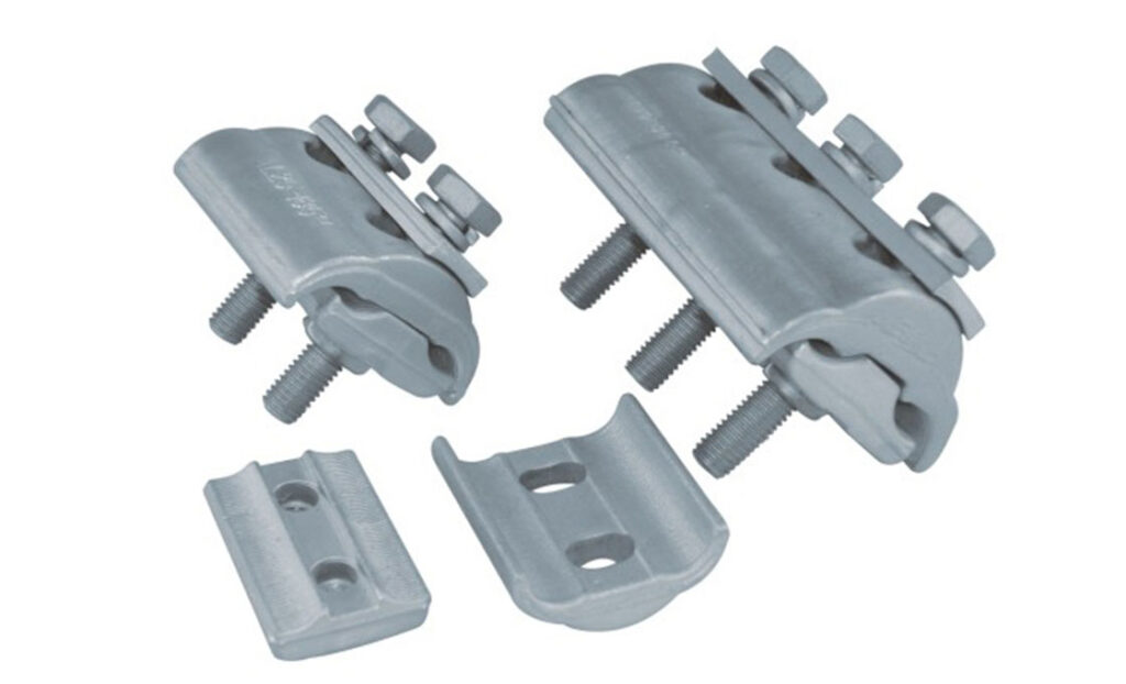
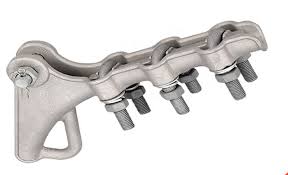
Parallel groove clamps for high-voltage transmission towers involve several components working together. They create a secure and reliable connection between conductors and cables. The available components vary depending on the manufacturer and design of the clamp. The main components of a parallel groove clamp are as follows.
- Body – this is the main component of the clamp that accommodates the other parts. It is from durable materials such as aluminum or coper alloy.
- Screws – screws and bolts help secure and compress the conductors within the clamp to create a reliable electrical connection.
- Grooves – the grooves are on the clamps body to accommodate the conductors to connect.
- Compression plates – these are metal plates on the conductors within the grooves to exert pressure on the conductors. This ensures a secure and low-resistance connection.
- Fasteners – extra hardware such as bolts, nuts and washers hep to secure the bolts to ensure a proper and stable connection.
Types of groove connectors
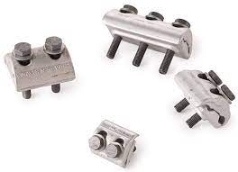
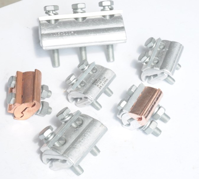
There are several types of heavy-duty parallel groove clamps. Each designed for specific applications and conductor sizes. The type also varies depending on voltage rating and the environmental conditions. Additionally, it is advisable to consult professionals for advice on which type to use for your particular project. The types may also vary depending on the material used during manufacture. The main types by materials include aluminum parallel groove clamps and copper parallel groove clamps. The following are the common types of the parallel groove connectors.
Bolted parallel groove clamps – these are the clamps that use bolts and screws to secure the conductor within the parallel grooves.
Wedge-type parallel groove clamp – this clamp uses a wedge mechanism to compress and secure the conductors. They are mostly used in high voltage applications.
Compression type parallel groove clamp – this clamp features a compression mechanism. This mechanism helps to distribute pressure evenly along the conductors within the grooves.
Application areas of the parallel groove connectors
Parallel groove clamps work in various applications where secure connections between the conductors is necessary. They provide reliable electrical connections and mechanical strength. This ensures efficiency, safety and performance of electrical installations. The following are the common application areas of these clamps.
- Electrical distribution networks – the clamps assist in connecting cables within the distribution panels, service entrances or distribution boxes.
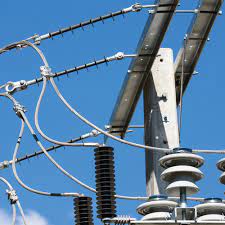
- Overhead power lines – parallel groove clamps ease the connection of conductors. This ensures reliable electrical continuity and mechanical strength.
- Telecommunications systems – the clamps help in connecting the coaxial cables and grounding wires. They also help secure electrical connections in networks.
- Transmission towers – the clamps help to secure the conductors to tower structures. The connection ensurea stability and integrity of the lines.
- Renewable energy – the clamps help to connect cables between solar panels, wind turbines, inverters and power distribution equipment.
- Railway electrification – the clamps connect the catenary wires to the supporting structures. This ensures reliable and stable electrical connections in the train operations.
- Industrial applications – applications such as manufacturing facilities, power plants and petrochemical plants use parallel groove clamps. They help to connect the conductors in power distribution systems, track control centers and equipment installations.
Installation process of parallel groove connectors
The installation process of the parallel groove clamps involves a series of steps for safe connections. It is advisable to refer to manufacturer’s installation instructions, guidelines and safety procedures specific to the clamp. Additionally, you should consult professionals in the industry for guidance on industry standards and local regulations for safe installations. The following are the main steps in the installation process.
- Prepare the conductors and ensure they are clean and free from any debris.
- Select the parallel groove clamp matching the conductor size and type specified for the installation.
- Place the parallel groove clamp in the desired location on the conductor. Also, ensure the grooves align with the conductors for proper fit.
- Insert the conductors into the grooves of the clamp and ensure they are properly seated within the grooves.
- Tighten the bolts of the clamp using the suitable tools to compress the clamp and create a secure grip on the conductors.
- Ensure the insulating material is properly positioned over the clamp body to provide electrical insulation.
- Inspect the installed groove clamp to ensure that the conductors are securely held within the clamp and that the clamp is properly tightened.
- Conduct electrical testing if necessary to ensure the integrity of the connection.
Selecting the best parallel groove conectors

The selection process of the parallel groove clamp should ensure the chosen clamp is suitable for the specific application, conductor size and environmental conditions. This ensures a secure and reliable electrical connection. The selection process of the clamp involves a series of factors to consider as discussed below.
- Regulate the size and type of the conductors to connect using the clamp. Consider factors such as conductor diameter, cross-sectional area and the number of conductors to join.
- Determine the rating of the conductors to select the clamp that can handle the probable electrical load without overheating.
- Consider the material composition of the conductors and the clamp. Ensure it is compatible with the conductor material to prevent galvanic corrosion.
- Evaluate the environmental conditions where the clamp will install by considering factors such as temperature, humidity, etc.
- Check the mechanical strength requirements for the application which includes tension, vibration or other mechanical stresses. The clamp should provide strength and stability to withstand these forces.
- Ensure the clamp complies with the industry standards, regulations and electrical codes of the installation.
- Consider the manufacturer’s recommendations and guidelines n conductor sizes and torque values for tightening.
Frequently Asked Questions
What is a parallel groove clamp?
A parallel groove clamp is an electrical connection used to join two conductors in parallel. They provide a good electrical connection and prevent the conductors from sliding out of the clamp.
What are the common components of the parallel groove clamps?
Clamp body
Bolts
Grooves
Compression plates
Fasteners
What are the benefits of parallel groove clamps?
Secure electrical connection
High current carrying capacity
Mechanical strength
Easy installation
Corrosion resistance
Easy maintenance and repair
Compliance with standards
What are the limitations of parallel groove clamps?
Conductor size limitations
Installation complexity
Potential corrosion
Limited voltage rating
Limited adjustment capability