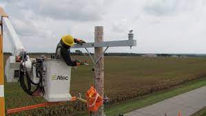
A crossarm brace is a component used in power transmission lines to provide extra support and stability to the electrical crossarm. They are horizontal beams attached to power poles and carry electrical wires. A crossarm brace is from steel or aluminum that helps resist rust and corrosion. They also work with other fasteners such as bolts, nuts and washers which helps prevent crossarm from rotating during high winds. This enables the devices to distribute the weight of the wires evenly. A crossarm brace helps to maintain the proper alignment of the conductor. It ensures integrity and reliability of the power transmission lines. it involves a fiberglass rod that connects the top part of the crossarm to the pole.
Components of a crossarm brace
The components of the crossarm brace varies depending on the manufacturer, type of transmission line and the local regulations and standards in the region. The components work together to provide extra support and stability to the crossarm. They also maintain the integrity of the power transmission line. The following are the main components of the crossarm brace.
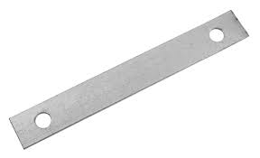
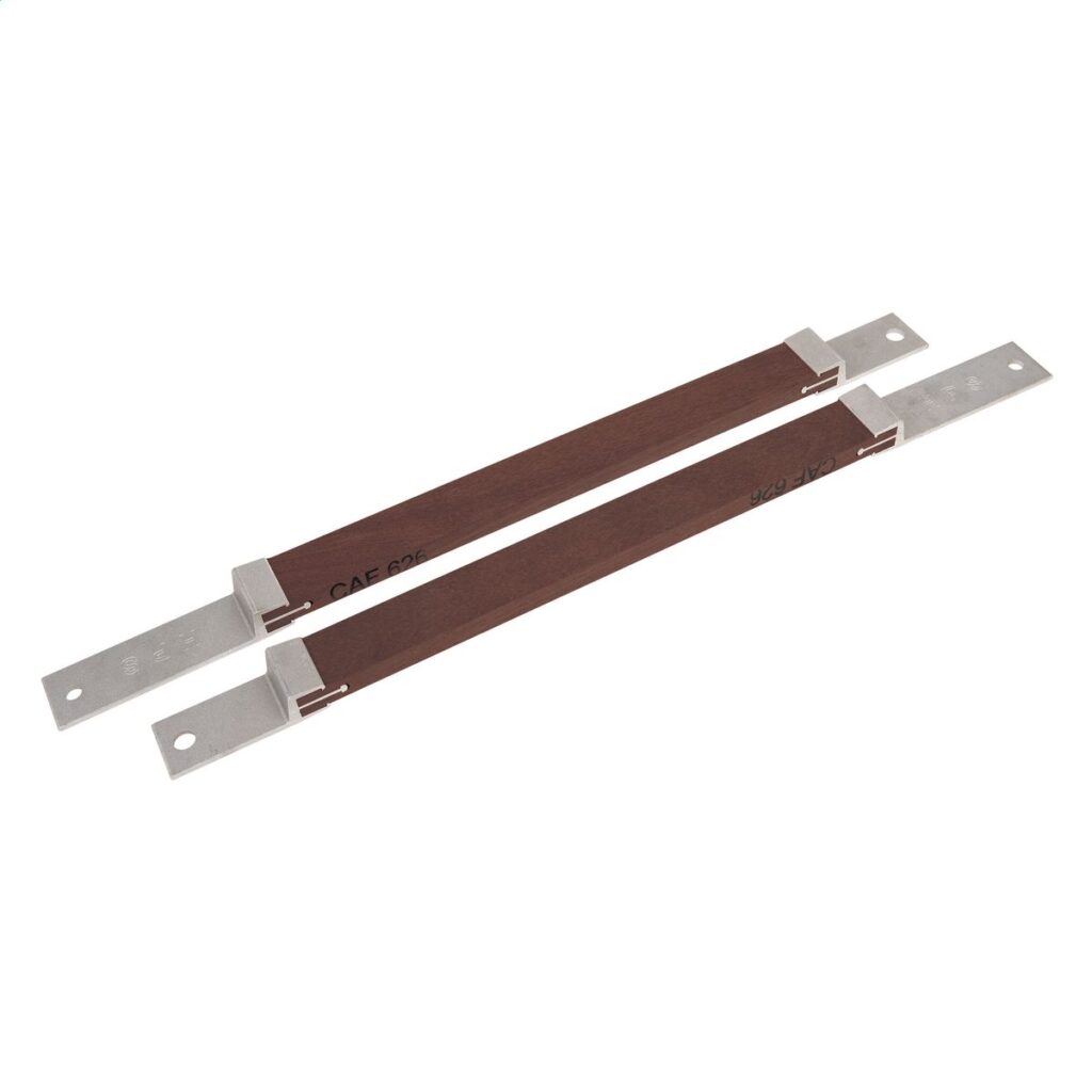
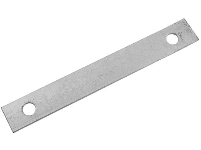
- Diagonal rod – this is the main element of the brace with a long metal rod that provides the diagonal support. It is usually straight or curved to form a triangular shape when installed.
- Clevis pin – this is a U-shape metal fitting with holes that attaches to the ends of the diagonal rod.
- Insulators – an insulator may work between the diagonal rod and the crossarm to electrically isolate the brace from the conductors.
- Fasteners – fastening devices such as bolts and nuts help to secure the clevises to the crossarm and the pole.
Types of crossarm brace
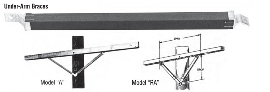
The specific type and design of the crossarm brace depends on factors such as the design requirements, structural considerations, environmental conditions and local standards. The type of fiberglass crossarm brace selected depends on the environmental conditions such as high winds or wind loads. The common types of crossarm braces include:
Single diagonal brace – this is the most common and basic type of brace. It consists of a single diagonal rod connecting the top part of the crossarm to the pole.
Double diagonal brace – this type consists of two diagonal rods arranged in an “X” shape. It provides stability and strength in areas prone to high winds.
V-type brace – this one has a “V” shape used for corner or angle structures in power transmission lines. This provides support and reinforcement for the crossarm at the corner. It also allows for a smooth change in direction of the conductors.
Knee brace – this is a short diagonal rod that connects the bottom part of the crossarm to the pole. This helps provide extra lateral support which prevents bending of the crossarm.
H-frame brace – this consists of two diagonal rods like the double diagonal brace which provides stability to the crossarm.
Application areas of the brace
Steel crossarm braces are crucial in construction of the power and distribution systems. They ensure the reliable and safe operation. They also cut the risk of power outages or damage to the conductors and help maintain the efficient transmission of electricity. The following are the main application areas of the brace.
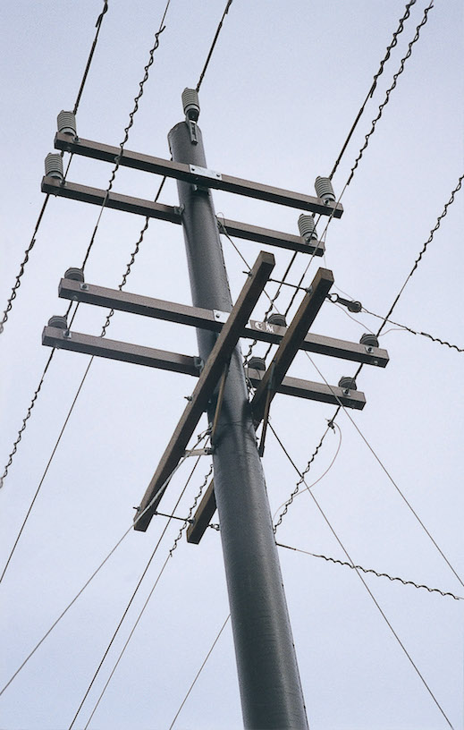
- Utility poles – high-strength crossarm provide support and stability to the crossarm holding the electrical conductors on utility poles. They help prevent sagging, twisting or excessive movement of the crossarm.
- Transmission tower – crossarm braces work on transmission towers to reinforce crossarms. They also help maintain the proper alignment of the conductors and ensure the structural integrity of the tower.
- Telecommunication lines – corrosion-resistant crossarm braces work in these applications to support the weight of the cables and wires on the crossarms.
- Street lighting – crossarm braces help to support the weight of the lights and fixtures attached to the crossarms.
- Corner structures – adjustable angle crossarm is the best crossarm to use for corner structures. They allow easy customization of the brace angle to accommodate changes in direction.
- Angle structures – the brace reinforce the crossarms to assist in maintaining the appropriate positioning and alignment of the conductors.
Fiberglass crossarm brace installation guide
Installation procedures vary depending on the design requirements, manufacturer’s instructions and applicable regulations. The installation should be carefully handled to ensure proper alignment, secure attachment and adequate support. Also, it is advisable to consult with the qualified experts for guidance when installing the crossarm braces. The following is a basic installation procedure for the brace.
- Prepare the tools and equipment which includes wrenches, fasteners, clevis pins and insulators following the safety precautions.
- Assess the installation location and ensure the components are free from debris and other contaminants. Also consider factors such as conductor tension, wind loads and ice loads.
- Position the crossarm brace diagonally from the top part of the crossarm to the pole. Also, ensure it forms a stable triangular shape when installed.
- Attach the clevises to the ends of the diagonal rod using bolts and nuts to secure the connections.
- Following the manufacturer’s instructions, attach the insulator between the diagonal rod and the crossarm if required.
- Attach the brace to the crossarm and the pole by placing the clevis pins through the holes in the clevises. Secure them tightly with cotter pins or other locking mechanisms.
- Inspect the installation to ensure that all components are properly installed and tightened. Ensure the race forms a diagonal support aligning with the crossarm and the pole.
Selecting the best high-resistant crossarm brace
The selected crossarm brace should ensure stability, reliability and safety of the power transmission line. The selection process should be carefully examined to ensure they meet the desired intentions for your application. You should consult with professionals in the electrical industry for advice on the best crossarm for your project. The following are some of the key factors to consider when selecting the best crossarm brace.
- Determine the expected load capacity and stress on the brace. Consider factors such as weight of the conductors, wind loads, ice loads and other conditions.
- Determine the required length and angle of the brace based on the specific configuration of the line. This includes distance between the crossarm and the pole and any angles on the line.
- Check the compliance with industry standards by local authorities to meet the necessary safety and performance standards.
- Select crossarms made from materials such as fiberglass or steel for stability, strength, resistance to corrosion and durability.
- Ensure the brace is compatible with the pole, tower for attachment. Consider factors such as dimensions, attachment points and load-bearing capacity of the components.
- Select the braces from manufacturers with a good reputation in producing high-quality products. They should also offer guidance and customer services.
Frequently Asked Questions
What as a crossarm brace as used on power transmission lines?
A crossarm is a hardware used to provide extra support to an electrical crossarm and help prevent the crossarm from rotating in high winds. They also help to distribute the weight of the wires more evenly.
What are the common types of a crossarm brace?
Single diagonal brace
Double diagonal brace
V-type brace
Knee brace
H-frame brace
What are the benefits of the crossarm brace?
Even load distribution
Longevity and durability
Flexibility and adaptability
Compliance with standards
Cost effective
Enhanced stability
What are the limitations of using a crossarm brace?
Complex installation
Maintenance requirements
Environmental factors
Design limitations
Compatibility issues